Trial and Error. Lots of it.

[This post started as a progress report and ended up being more of a mental progress report. My next post will provide details about the current hardware and software of the KR01 robot.]

I just got another package in the mail. A couple of pieces of plastic. 3mm black Delrin. Very nice plastic.

While building the KR01 robot there’ve been a few lessons learned. One is that any notion of a “final design” was pretty foolish. If anything I’ve been constantly changing things. Donald Knuth, author of The Art of Computer Programming, famously wrote that “premature optimization is the root of all evil”, but we’re not talking here about optimisation: I’ve simply been trying to come up with functional hardware and software. Even for a small robot that’s proven to be anything but trivial. And the mistakes I’ve made have been due to both complicated and very trivial reasons.

ThunderBorg connections
What’s wrong with this picture?

Here’s a simple quiz (one that I’ve failed, twice):

Okay. You have a motor controller with connections labeled M1+ and M1-, M2+ and M2-. I’ve designated the port (left side) motor as M1 and the starboard (right side) motor as M2. You connect the white wire of the port motor to M1+, the black wire of the port motor to M1-, the white wire of the starboard motor to M2+ and the black wire of the starboard motor to M2-, just like in the photo. Correct? BZzzZZttt! Wrong. Can you guess why, or what will happen?
Answer: If you connect both motors to the controller in the same way (same polarity) and tell both motors to move forward, well, they will do exactly as you ask. Except that “forward” for the port motor means forward around the central axis of the robot, so the robot will spin counter-clockwise in place. Like many things this seems perfectly obvious, in retrospect. In retrospect.

I’ve been a software developer for many years, and iterative design is something I’ve long believed in, or at least have (by default) practiced. That is, you don’t get it right the first time, or the fifth. You keep hammering away until some portion of the work is done and then just move on to the next bit. Perseverance furthers. This isn’t that silly waterfall vs. Agile argument. It’s good to plan ahead. You need to plan, as much as you can. But at the beginning you can’t possibly see the road ahead. A hypothesis, a direction, yes.

Unlike software systems, with robots we have both hardware and software to deal with, and the entire approach is different, compared with say, a client-server infrastructure for a national weather service (which I have some experience with). The latter is enormously more complicated, but writing a robot operating system for a custom-built robot is just plain tricky, both getting the hardware functional and getting the software to do what you want. The hardware is a myriad of compromises of space, weight, cost; the software is reacting to an ever-changing series of sensor events, in real time. The more sensors, the more complicated things become. The motor controller softare can itself be quite a challenge.

It’s pretty tricky to create even a simple line-following behaviour, where there’s a single program that reads the values of two infrared sensors and alters the speed of two motors.

NASA’s Sojourner robot, which landed on Mars in 1997, sported an 8085 8 bit microprocessor with a 2 MHz clock (rated 100,000 instructions per second), addressing 64 KB1 of memory, 64 KB of RAM for the main processor, 16 KB of radiation-hardened PROM, 176 KB of non-volatile storage, and 512 KB of temporary data storage2. By comparison, the Raspberry Pi 3 B+ in the KR01 costs all of US$35 but is many orders of magnitude more powerful — somewhere over 200 million floating point instructions per second — with a 64 bit processor, a 1.4 GHz clock and 2 GB3 of memory. Rather than an SD card I’m using a Samsung 250 GB SSD for data storage, which costs about US$80. The Raspberry Pi is running a Linux operating system and I’m programming the robot in Python, not assembly language. So even if my budget is miniscule, I have some very significant advantages over NASA in the mid-1990s. The limitations of my project are entirely me.

I have no idea how difficult it must be to design an autonomous robot like NASA’s Perseverence robot, where there are seven large scale instrument systems, a five-jointed robotic arm and 23 cameras. It’s not a remote controlled robot (called telerobotics, basically a drone), as while it can be commanded, it’s autonomous: it can “think” for itself. It also weighs 1 metric ton, its power supply uses 5 kg of plutonium, and its mission has a budget of US$2.04 billion. Of course, it’s going to Mars. My KR01 only needs to navigate my lounge.

Perseverence would just fit in my lounge, if I moved my sofa (photo: NASA)

As is my nature, I jumped in headfirst and built a robot with quite a few sensors and hardware that I’ve been changing almost continually since I started. The photo at the top of this post is testament to the number of changes: it’s the “motherboard” of the robot that held the Raspberry Pi and all of the sensors that weren’t attached to the front bumper, and I’ve been almost continuously shifting things around both under and over that 3mm plastic boundary. Lots of holes.

While drilling all those holes, I learned a few things:

  • Everything is a compromise when it comes to the real world. Designs are abstract. Even if you know exactly what your goals are when designing a robot, the choice of materials, motors, batteries, sensors, and how they all fit together into a single hardware system, well, you’re not going to get it right the first time, and only by repeatedly failing will you arrive at a solution that kinda works. And it will only work some of the time. Then you go back and make some changes and try again. Repeat. And then once you’ve learned things by doing all that, your goals change.
  • You don’t know how things will go until you actually try it out. Design and its implementation are never the same. Robots and systems comprised of purely software are different in some rather profound ways. Rodney Brooks talked about two aspects of robots: situatedness and embodiment in his 1991 paper Intelligence Without Reason (see Some Notes on Artificial Intelligence ). This means that we’re not programming for an abstract system, we’re designing a control system for something that exists in the real world and has to deal with real world physical limitations and obstacles, where how long something takes to happen is affected by many factors, like floor surfaces, traction, and battery life. Things are often unpredictable. No two DC motors perform exactly the same, and are affected by things like heat and gear train friction. Sensors don’t perform exactly as we might think, and can be affected by bright lights, dust, radio frequency interference. There are wood floor to carpet transitions. Cat hair.
  • There’s going to be hardware and software bugs. I’m pretty meticulous, I like to think. But the number of mistakes I’ve made while building this robot, even after double- and triple-checking things, is rather humbling. To be fair, not everything was a mistake, sometimes it was trial and error, but there’ve been quite a few errors as well. For example, I’ve made mistakes creating wiring harnesses, forgot to provide power to sensors, drilled the holes for something and found it was too close to something else, and found a couple of push connectors that when pushed onto the connector pin just backed out of their housings and failed to make the connection. Sometimes these mistakes were obvious, some took awhile to discover and fix.
  • Things keep changing. Things wear out. You think you can bundle up those wires with a nylon wire tie? Think again. When you make a change tomorrow you’ll need to cut it off. This isn’t a reason to avoid the wire tie, just know that nothing is permanent, nothing lasts. This is also a central premise of Buddhism. Stay flexible, design for change.
  • Expect the unexpected. Robot hardware and software just doesn’t do what you think it’s going to do. It just doesn’t. Something always jumps up and grabs your ankle, and you’re sitting in your lounge with a mint julep, not prowling a desolate graveyard in a howling storm.
  • Learn from those who’ve gone before you. There’s little point in making mistakes others have already made. You can go it alone and make all those same mistakes, or do a bit of research to learn what to avoid, and also to seek inspiration.
  • Don’t be afraid to ask for help. Similar to that last item, there’s a lot of experience out there. If you’re polite people are usually happy to answer your questions, or point you at resources and documentation.
  • Try to stay organised. By this time I’ve got a lot of spare parts, nuts and bolts, sensors I haven’t yet tried out, or tried out and am not currently using. Just as in any shop, it’s smart to keep sort things out, keep things in divided containers, put your tools away when they’re not in use.
  • Stay within your budget. Have some idea of what you want to spend on your project, add a 20-50% percentage overrun, and design your robot to reasonably fit within that budget. All the miscellaneous adds up.
  • Be prepared. Make sure you have the right tools for the job. Have some spare parts handy. I’ve purchased extra 2.5mm, 3mm and 5mm nuts and bolts, washers, lock washers, nylon lock washers. A packaged set of 2.5mm nylon standoffs and a selection of LynxMotion 3mm aluminum standoffs in various lengths. I got a good quality soldering iron, and already had a multimeter and oscilloscope (the latter has proven pretty handy, if not strictly necessary). I have a well-lit, ergonomically-correct workspace. Power tools.

Hmm. I’m not sure if that list was really about building robots.

Here are some robot-specific ones (though suspiciously still generally-applicable):

  • Balance is important. You need to position the heavy objects (like batteries) so that the weight is over the center point of the robot, or if your robot is two wheeled with a trailing ball or wheel caster, low and slightly behind the main axle. If the weight is not on-center the robot’s motion will be affected.
  • Make sure you have enough power, and the right power. The Raspberry Pi needs a regulated 5 volt power supply: you’ll either need a USB “power bank” or a 5 volt regulator running off of a higher voltage battery. Your batteries might be lithium ion or lithium polymer supplying 3.7 or 7.4 volts, or nickel metal hydride (1.2 volts each) or alkaline AA batteries (1.5 volts each). An AA battery holder can hold four, six or more rechargeable or alkaline batteries supplying anywhere from 4.8 to 12 volts. Four AA rechargeable batteries provide 4.8 volts (not enough) and four alkaline AA batteries provide 6 volts (too much). Or like the KR01, you could use a power tool battery supplying 12 or 18 volts (which in reality seems to be around 20 volts). Your motors will likely need 6, 9 or 12 volts. Many of the motor controllers are configurable to handle a larger input voltage than the motors can handle, but this still requires care and proper configuration. Beyond voltage is current: how long your robot will run depends on the capacity (in amps or milli-amps) of your battery supply. Do you use a single battery for both the microcomputer/microcontroller as well as the motors? If you only want your robot to run for a few minutes at a time your battery capacity can be significantly lower.
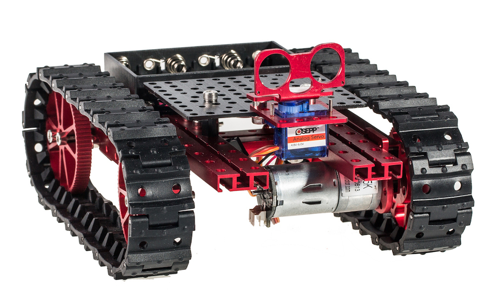
  • Measure three times, cut once. Even with careful planning it’s easy to cut something the wrong size, or drill a hole in the wrong place. As you can see from the photo of the KR01, there’s not a lot of extra space anywhere on the robot, and I had to shift things around a lot to get things to fit. If there are any moving parts (like a servo-mounted ultrasonic sensor or camera), you need to be sure there’s enough clearance so that it won’t run into some other part of the robot.

Hmm. I might add to this list as time goes on but I can’t think of anything else right now. My beer is still cold, and only half full.

My next post will provide a progress report on the KR01 robot.

From Failure, Success

KRZ-01 Robot

There’s been another mishap around here. I guess building robots has its ups and downs and last week was no different.

I’m kinda ashamed to say that while I was working on the KR01 robot I’ve now managed to burn out two Thunderborg motor controllers and one Ultraborg servo controller. Well, not quite “burn out”. The motor controller parts of the Thunderborgs still work but the RGB LED used to display the battery level has somehow gotten fried on both units, and the Ultraborg (which is used for sonar and servo control) seems to have died during the first Thunderborg catastrophe (sympathetic death). I have no idea really how this has happened, but of course the only real possibility is that I’ve done something wrong. I mean, I’ve been very careful with checking my wiring before applying the power, but at some point I must have got my wires crossed. The PiBorg folks who make these boards have been quite helpful and I’m sending them back to the UK to see if they can figure it out. But that will take awhile.

King Ghidorah anatomy by Shoji Phtomo
Not to be confused with Monster Zero 1

This means that for at least a few weeks I would be without a robot (the horror)! I really can’t have this happening just as I’m getting the robot operating system up and running. So last weekend I went ahead and built out one of my design prototypes, which I’ve been calling the KRZ-01 (Kiwi Robot Zero), as it’s based on a Raspberry Pi Zero W. It uses a Picon Zero for a motor controller, a Pimoroni Breakout Garden to mount some of its sensors, and a trio of infrared detectors rather than a front bumper.

Happily, the build posed only a few problems and I had it up and running rather quickly. I rewrote the Python modules that had been used to control the KR01’s motors to instead use the Picon Zero and I had it dancing around on the carpet today for the first time:

KRZ-01 Motor Control Demo

The KRZ01 is meant to be small and relatively cheap, but still have the ability to carry some impressive sensors. It actually isn’t a whole lot less capable than its larger sibling, the KR01. Without including shipping the parts come out around NZ$250, so it’s not the cheapest robot you could build but it’s got a lot of functionality2.

Side View of KRZ-01
Side View of KRZ-01

It’s based on a Raspberry Pi Zero W, which has 500MB of memory and supports both WiFi and Bluetooth. The OS is Raspbian Linux. The Picon Zero motor controller and a Breakout Garden Mini are both mounted on a Mini Black HAT Hack3r breakout board. This is an extremely compact setup. You can see this on the side view photo.

The sensors include: three Sharp infrared detectors; a VL53L1X Time of Flight (ToF) distance sensor mounted on a micro servo, which can measure distance up to about 4m with a 25mm accuracy (this is the same sensor I used on my night light); and two 298:1 ratio micro gear motors with encoders so we can measure how far we’ve travelled.

Bottom view of KRZ01
Bottom View Showing the Motors and Motor Encoders

There’s still two free I²C Breakout Garden sockets so additional sensors can be swapped in and out without any soldering. I added a couple of 11×7 LED Matrix boards as status displays but they’re hardly necessary. The whole thing runs on a common USB battery. The chassis is made out of 3mm Delrin plastic. For locomotion it uses a pair of Moon Buggy wheels, a lightweight plastic ball caster in the front, a heavier stainless ball in the back (so its balance is towards the back caster).

Since the robot supports WiFi I connect to it remotely using ssh, which is how I’ve been installing and loading its software, starting and stopping programs, and shutting it down 3. Remarkably, the Raspberry Pi W includes a tiny HDMI connector so I could plug it into a monitor, but that hardly seems necessary. This seems like a command line robot.

The chassis is 75mm wide and 120mm long. Without a battery the whole thing weighs 120 grams. For comparison, that’s 17 grams less than my iPhone 5. I have a 5200mAh battery that weighs 136 grams and a 4400mAh battery that only weighs 40 grams, so unless battery life is an issue I’ll probably use the smaller battery. I have a 10000mAh battery (200g) that would last many hours but I can’t imagine leaving the robot alone that long. What kind of trouble could it get into?

For more information about the KRZ01 Robot, visit its NZPRG wiki page.

Note: as of today the NZPRG has its own YouTube Channel.

Edit: after some back in forth in email and finally posting the boards back to PiBorg in the UK, I learned from them that what seemed to have happened was that the UltraBorg tested as faulty, and that was apparently what was burning out the LEDs on the ThunderBorgs. They’ve since sent me replacements for both and all is working well now. A well-deserved thank you to PiBorg for their patience and help!

After Despair, Some Joy

This article is the fourth in the multi-part series “Building the KR01 Robot” ( 1 | 2 | 3 | 4 ). Further articles can be found tagged “KR01“.

Hsü

Sometimes when you’re experimenting you fail. Sometimes over and over. I had two failures this week, one that had a solution and one that didn’t seem to. But as the I Ching says: perseverance furthers1.

Tank Treads

Celebration of a tank failure…

After some deliberation I’d decided to base my robot on a tank. I’d considered the benefits of a “dual-differential drive configuration, balanced by a non-driven tail wheel caster” on David Anderson’s SR04 robot and thought the OSEPP Tank Kit might be able to provide a suitable drive platform for my robot. One of the requirements of being able to determine the location of your robot is to accurately know how far its left and its right drive motors have traveled. This is necessary in order to perform odometry.

The SR04 has a left drive wheel and a right drive wheel and can rotate in place if the wheels turn in opposite directions (David’s robot impressively can spin in place on a table without changing position). A tank is able to do the same but requires a lot of tread slippage, and this “odometry error” would need to be accounted for somehow, perhaps using another type of locational awareness.

I hadn’t thought of the other problem, and there was a bit of delay in even finding out that there was another problem (one of those “unknown unknowns”). During the assembly of the robot I’d taken the silicon tank treads off a few times, and one morning one of the tread pieces had torn, and it’d been my last spare. I’d contacted OSEPP and they’d been very nice in sending out some replacements. Being this is New Zealand shipping things here from North America took awhile.

By the time the replacement treads arrived I’d gotten the robot to the point where it could perform its first test drive, so I put on the tank treads, wrote a quick Python program to move forward, turn around (do a 360 degree turn) and come back.

I put it down on the carpet and executed the program. The robot moved forward just fine (baby steps!), but as soon as it began to turn around, to my horror the treads slipped and twisted up, partly came off and then caught under the robot. I hit the kill switch (actually, Control-C from the ssh session), put the treads back on and tried it again. Same result. It was better on a wooden floor, but if the rotation was too fast it still sometimes did the same thing.

NZ Tomtit
New Zealand Tomtit
(image: Graham Commins (CC))

Now, I can’t blame the OSEPP people for this. I measured my robot and without a battery it weighs 1.7kg. With the smaller 12 volt Makita power tool battery it’s up to 1.92kg, and with the Makita 18v 3Ah battery2 it tops the scale at 2.35kg (5.2 lbs). If one watches the OSEPP Tank promo video on YouTube their little tank zips around with just an Arduino and a six AA cell battery pack, so it’s carrying nowhere near as much hardware. I’d be comparing a kererū with a tomtit. Unfair. I think a robot with a weight similar to the original kit would be fine.

The kererū, or New Zealand wood pigeon,
(image: NZ Forest and Bird)

My big fat kererū just couldn’t use the tank treads. I’d considered the tread slippage problem (but not the treads-falling-off-disaster) and ordered four of the OSEPP silicon wheels, and after some floor and carpet testing found that they would work. There’s enough slippage on wood floor or carpet that the four wheels do a reasonably good in-place rotation.

Thank goodness. I didn’t want to have to go back to the drawing board.

The Other, Seemingly Intractable Problem

OSEPP Motor Encoder: four connections!

The other problem was with the motor encoders. These are tiny Hall Effect sensors mounted to the motor shaft (before the gearbox) and are meant to provide a pair of waveforms (labeled A and B) that permit a determination of engine direction, speed and the number of times the shaft has rotated.

I’d spent days debugging this. I have this cool old Iwatsu SS-5710 oscilloscope I bought at a local pawn shop. It’s everything you want in an oscilloscope and more: complicated, mysterious, lots of knobs, bright image, nice lines, good coloring, even engages in scintillating dinner conversation. Okay, maybe not that last one.

I’d tried everything to get a usable waveform off of the sensors. Tantalisingly, I was able to get some tiny waveforms, similar to those NASA receives from Mariner 9 at the edge of the universe. But not enough to peg a Raspberry Pi GPIO pin. I’d disassembled the robot, adjusted the encoders, tried adding a 74HC14 Schmidt trigger circuit (forgetting that the encoders already do this), nothing worked. Ugh.

This morning I was reconnecting the 6 pin IDC cable I’m using between the chassis and the platform holding the Raspberry Pi, and I remembered that there were six pins. Six pins. The left and right motors each had an A and a B (i.e., A1, B1, A2, B2). What had I used the other two pins for?

Oh yeah… power.

I hadn’t provided power to the motor encoders. As soon as I connected ground and 5 volts to the encoders and fired up the robot while connected to the Iwatsu, lo and behold: I had some square waves. Success! If it’d been later in the day I would have cracked open a beer.

Motor Encoder Output
Finally, some square waves!

I then rummaged through all manner of half-completed Python scripts to find one that with some slight modification was able to count up and count down as the motor drove forward and back. So… the robot now functional motor encoders.

Next: to begin figuring out how to write a PID Controller.

The Wiring Begins

first KR01 prototype

This article is the third in the multi-part series “Building the KR01 Robot” ( 1 | 2 | 3 | 4 ), and describes beginning to design and build the hardware of the KR01 robot project.

With the robot chassis largely complete (at least for now) I began to plan out where I’d mount the Raspberry Pi, motor controller and other PC boards.

Shakey the Robot

Historically, robots seem to generally have mounted their drive systems on the bottom of a horizontal platform, with their control systems on the top. You can even seen this on Shakey, the first autonomous robot, which was developed back in the late 1960s at Stanford Research Institute (SRI).

My modified OSEPP Tank Kit provided a horizontal area to mount parts but I’d have to drill into the aluminum1 and that seemed rather inflexible, and the mounting holes of the various components didn’t match that of the OSEPP beams, which use a 16mm grid.

I wanted to mount my components on something lightweight and non-conductive, cheap, and easy to modify and/or replace. Some kind of plastic seemed right. I could have used used acrylic (called “perspex” here in New Zealand) but it tends to be rather brittle and easy to crack or split, so I settled on Delrin (a trade name for polyoxymethylene plastic), which is a bit softer, tougher, and almost indestructible. Delrin is often used for making bearings.

The Lower Bits

One thing I learned long ago: it’s all very well to be able to build something but you also need to be able to disassemble it easily. I figured that I needed some way to gather the various wires from the motors and motor encoders in such as way that I could use detachable cables to easily remove the top platform from the chassis. So one principle I’m using on the KR01 is to try to use jumper wires and single and dual header pins for the connections, so that things don’t have to be permanently soldered together.

chassis interface pinout
Chassis Interface Board pinouts

For what I decided to call the Chassis Interface Board I planned to use two 6 pin IDC cables for the connections to the upper part of the robot and one of the AdaFruit Perma-Proto boards to hold all the parts and organise the wiring, which just happened to fit into the area available. I mapped out the pin layout and then soldered some header pins to the board. I also cut a bit of 10mm aluminum “L” section to hold the SPST power switch, the DPDT motor kill switch, and a status LED (you can see this in the photo below).

chassis interface board
The Power Controls (left) and Chassis Interface Board (right)

I ended up drilling two small holes (the horror!) in the aluminum rails to hold some nylon standoffs, then mounted the Chassis Interface Board and wired things up.

Even with all my planning I didn’t get it right the first time and had made a wiring mistake. Apart from the mistake, now that I’m done with these components, the nice thing is that because I’ve not soldered everything together (except in creating the components themselves) I can take it all apart when I decide to make a design change. And that’s bound to happen.

The Platform

I decided to mount my components onto a black Delrin platform using nylon standoffs, so I bought an assortment of 2.5mm black nylon standoffs from Adafruit there’d be no issue with short circuits. A robot used for off-road or robot combat might need to use metal for strength, but the KR01 is strictly a domesticated house robot2

The closest plastics store in Petone didn’t carry sheet Delrin but Macplas up in Auckland did. After a brief phone conversation about which plastics were most appropriate for a small robot, I ordered some black 3mm Delrin for the platform and some clear 3mm polycarbonate for the front bumper. I find that when you involve people in the details of what you’re doing they can use their expertise to best help you.

component layout
Component Layout

Rather than start with the Delrin (which is kinda expensive) I prototyped the board first using a milky white nylon chopping board I bought at the Warehouse for $5. Yes, it occurred to me that I could have just used the nylon but the Delrin is thinner and much cooler. I mean, who makes a robot out of a chopping board?

I taped some paper to the plastic and laid out the various components, then drilled the holes. They say “measure twice, cut once” but I still made a mistake. So maybe it should be “measure thrice, cut once”, 3

Stuff Begins Arriving in the Post…

Early Prototype

This article is the second in the multi-part series “Building the KR01 Robot” ( 1 | 2 | 3 | 4 ), and describes beginning to design and build the hardware of the KR01 robot project.

Inspired by David Anderson’s SR04 robot (in particular, his YouTube video) I searched around for a suitable robot platform, the kind of chassis and motor that fit the scale of the design-in-my-head, and a few other factors. Having read David’s documentation of the project I rather liked his “very loose” design criteria:

  1. Survive in a wide range of (cluttered) human environments autonomously and continuously, without getting stuck.
  2. Provide a robust and reliable platform for developing navigation and behavior software.
  3. Be entertaining and aesthetic for the local human population.

I thought I’d have a go at updating what he’d done in 1998 to see what 22 years might have brought to progress in the world of “personal robots”. I’d been perusing the AdaFruit and Pimoroni websites and had seen all manner of pretty amazing sensors for prices I could afford. It was time to stop making Raspberry Pi night lights and try something more ambitious.

I admit to having strayed from one of David’s stronger design principles in the SR04, that being his “dual-differential drive platform with the geometry of an 11 inch circle” 1. That symmetry is valuable and I’m hoping that my tank-tread design (or four wheels if the treads don’t work out so well) won’t suffer. Watching the SR04 rotate continuously on a table without moving in place is pretty impressive. But I have to start somewhere. I can always modify the design…

OSEPP Tank Kit
The OSEPP Tank

So, I settled on an OSEPP Tank Kit. It’s a bit like Lego or Meccano in that the kit is provided as a set of red-anodised aluminum beams, some accessory plates and connector bits, using 4mm nuts and bolts to hold things together. There’s some flexibility in this, and OSEPP sells accessory kits. I bought an extra set of beams, as I knew of one deficiency in the Tank Kit I wanted to immediately change: it has four wheels but only two motors: the port motor at the front, the starboard motor at the rear.

Since David’s design uses a PID Controller I knew I’d need to use motor encoders, which was one of the reasons I chose the OSEPP kit: they offer a pair of motor encoders using Hall Effect sensors. I’d seen an image of two OSEPP motors and encoders mounted along a single beam, quite an elegant design. It seemed prudent to have both of the encoders on the same pair of motors (either the front or the rear). The Tank would have to be wider and I also wanted four drive motors, not just two. Using tank treads is not very efficient so I figured there’d be insufficient horsepower to drive a robot with only two.

In New Zealand orders from overseas can take anywhere from a few days to weeks in waiting, so I started making decisions and putting in orders. Locally I bought some stainless 4mm hardware from Mitre 10 and Coastal Fasteners. (See Vendors on the NZPRG wiki.)

The Kit Arrives

I’m not going to do one of those ridiculous unboxing videos. Yes, the box arrived. I opened it. I didn’t keep track much with videos or photos. I was playing, not performing.

prototyping in the kitchen
Playing on the Kitchen Table

The OSEPP kit is well-designed, though it’s impossible not to leave a bit of rash on the red anodisation. If you simply built the Tank Kit as intended this wouldn’t be an issue so much, but I tried at least four or five different permutations before settling on one design, and then had to modify it several times when I tried adding things like the front bumper supports and the mount for the power switches.

Beautifully Machined Wheels

The hardware is fun to work with. Not like Lego, where it can be a struggle to connect things securely, the OSEPP kit’s parts are held together by 4mm stainless steel nuts and bolts.

I locally sourced some stainless lock nuts (also called “nyloc nuts”) as I prefer them to the serrated flange nuts provided with the kit (though these work just fine too).

The Motor Encoder kit hadn’t arrived so I built it without remembering that photo I’d seen with the single beam holding both two motors and their encoders. The design as shown above on the kitchen table had no place to mount the encoders. The photo below shows each pair of motors mounted to a single beam, with the motor encoders attached to the front (top) pair.

Front and rear pairs of motors, you can see the encoders mounted on the motor shafts of the front pair. The left and right motors are wired together so they’ll appear as a left drive and a right drive.

When the motor encoders finally arrived I did another round of building and came up with what I thought was the final chassis, but even that had to change once I tried to mount the tank treads. As you can see, there’s not much clearance between the front bumper and the treads. And of course, the front bumper was only a stand-in until I could begin building the real bumper.

Next time: we begin the wiring and mounting the platform for the circuitry…

Some Notes on Artificial Intelligence

[These are some still-disorganised notes on Robotics, Artificial Intelligence, and Knowledge Representation that will likely be moved over to the wiki once it’s up and running. Likewise, at the bottom are some references, which will also end up on the wiki…]

“SMPA: the sense-model-plan-act framework. See section 3.6 for more details of how the SMPA framework inuenced the manner in which robots were built over the following years, and how those robots in turn imposed restrictions on the ways in which intelligent control programs could be built for them.”

— Brooks 1985, p.2

From Brooks “Intelligence Without Reason” [Brooks 1991]:

“There are a number of key aspects characterizing this style of work.

  • Situatedness: The robots are situated in the world — they do not deal with abstract descriptions, but with the here and now of the world directly influencing the behavior of the system.
  • Embodiment: The robots have bodies and experience the world directly — their actions are part of a dynamic with the world and have immediate feedback on their own sensations.
  • Intelligence: They are observed to be intelligent — but the source of intelligence is not limited to just the computational engine. It also comes from the situation in the world, the signal transformations within the sensors, and the physical coupling of the robot with the world.
  • Emergence: The intelligence of the system emerges from the system’s interactions with the world and from sometimes indirect interactions between its components — it is sometimes hard to point to one event or place within the system and say that is why some external action was manifested.”

Brooks notes that the evolution of machine intelligence is somewhat similar to biological evolution, with “punctuated equilibria” as a norm, where “there have been long periods of incremental work within established guidelines, and occasionally a shift in orientation and assumptions causing a new subfield to branch off. The older work usually continues, sometimes remaining strong, and sometimes dying off gradually.”

He expands upon these four concepts starting on page 14:

  • The key idea from situatedness is: The world is its own best model.
  • The key idea from embodiment is: The world grounds regress.
  • The key idea from intelligence is: Intelligence is determined by the dynamics of interaction with the world.
  • The key idea from emergence is: Intelligence is in the eye of the observer.

I might note that Brooks’ criticisms of the field of Knowledge Representation reflect my own findings, observed during the four years of my doctoral research on KR at the Knowledge Media Institute.

It is my opinion, and also Smith’s, that there is a fundamental problem still and one can expect continued regress until the system has some form of embodiment.

— Brooks 1991

The lack of grounding of abstract representation is evident from the almost complete
lack of the KR researchers to even bother to definitively explicate the two terms in the field’s title: “Knowledge” and “Representation”. How can one rationally explore a field when one doesn’t yet know what knowledge is, or where there is no epistemologically-sound definition of the word representation? The greatest related advances in that field belong to the likes of C.S. Peirce, John Dewey, Wilfred Sellars, Richard Rorty and Robert Brandom, but this seems (at this point in time) to be still disconnected to the concept of “embodiment” as explored in robotics (but I’m hardly the person to judge that issue). So it’s grounded neither in mathematics 1 nor in the real world.

I must agree with Brooks, that embodiment is a necessary precondition for research into intelligence. Brooks’ paper was from 1991, my doctoral programme began in 2002. I wish I’d read his paper prior to 2002. I met Doug Lenat in 2000 and over dinner in Austin we discussed the idea of working for his company, Cycorp (the corporate home of the Cyc Ontology). The whole thing is a giant chess set, a massive undertaking that as of 2020 is still essentially doing what it did when I saw it for the first time at SRI in 1979; it’s as Brooks says, it’s just followed the advances in computing technology but not really provided any real breakthroughs.

Regarding scale or size:

“The limiting factor on the amount of portable computation is not weight of the computers directly, but the electrical power that is available to run them. Empirically we have observed that the amount of electrical power available is proportional to the weight of the robot.”

— Brooks 1991, p. 18

References


Some Goals

What has become the New Zealand Personal Robotics Group began not long ago as a robotics project. So this is all pretty new. Below is a jumbled collection of some of my goals for the robotics project. Perhaps these goals will be shared by other people?

Meta-Goals

  • Explore ideas: both the philosophical as well as experience-based research within the field of Artificial Intelligence, specifically as related to robotics
  • Explore robotics hardware: the latest hobbiest-level sensors, motors, platforms, etc.
  • Explore robotics software: where have we gone since Rodney Brooks’ 1985 ideas about subsumption architectures [Brooks 1985], odometry using PID controllers [PID]?
  • Explore Self-Adaptive Software Systems
  • Learn the Python programming language

Goals

  • Try out various sensors and robot modules:
    • Time of Flight (ToF) laser distance sensors
    • infrared sensors (various distance ranges)
    • ultrasonic sensors (via PiBorg’s Ultraborg)
    • install Hall-effect motor encoders on the motor shafts, and write a Python-based PID motor controller
    • analog-to-digital converters
    • motion detector, to detect humans (and cats)
    • a robot front bumper, modeled after David Anderson’s SR04 robot [SR04]
    • motor control (via PiBorg’s Thunderborg)
    • Uninterruptible Power Supply (UPS) and battery management (via PiJuice)
  • Try out several robotic hardware platforms, for a low-cost, entry-level robot
    • OSEPP Tank Kit
    • Adafruit CRICKIT for Circuit Playground Express
    • robot chassis available from Adafruit:
      • Purple Aluminum Chassis for TT Motors – 2WD
      • Mini Robot Rover Chassis Kit – 2WD with DC Motors
      • Mini Round Robot Chassis Kit – 2WD with DC Motors
      • Mini 3-Layer Round Robot Chassis Kit – 2WD with DC Motors
  • motors:
    • OSEPP 25mm motors (part of the Tank kit), with encoders
    • yellow plastic motors
    • continual-rotation micro servos
    • Pololu micro gearmotors (1:298, with encoders)
  • Try out several robotic processor platforms, for a low-cost, entry-level robot
    • Raspberry Pi (Zero, Zero W)
    • Circuit Playground Express
    • Arduino
    • other microcontrollers, e.g., Adafruit ItsyBitsy M4 Express
    • Espruino WiFi (Javascript-based microcontroller)
    • MicroBit?
  • Explore use of I2C bus

Also see the page on Artificial Intelligence.

It All Started With a Night Light…

VL53L1X Time of Flight Sensor

I’d been playing around with Arduinos and Raspberry Pis for quite awhile, never with much of a purpose. The closest I came to a purpose was when a few months ago I’d found what for a robot enthusiast must almost be a dream, something called “Time of Flight” sensor, basically the operating part of a LIDAR (Light Detection and Ranging), one of the main sensors used in driverless cars. This one is smaller than a postage stamp, weighs a few grams, and uses a tiny laser to measure distance up to 4m at an accuracy of 20-25mm (or about an inch accuracy at 13 feet). How much does this thing cost? About US$19. Amazing.

To the consternation of my partner I ended up building a night light. We actually have a night light already, one of those plastic Japanese 100 yen things that work just fine, but I was having none of that.

The Pi Zero W RESTful Nightlight with Pew Pew Laser

It turned out to be a Raspberry Pi Zero W based nightlight with a RESTful web interface, three Red-Green-Blue (RGB) potentiometer controls for the colour of the 5 x 5 LED matrix running into an ADS1015 analog-to-digital converter, with the number of LEDs lit as a function of the distance the ToF sensor measures to your hand.

Overkill, absolutely. My partner? Not impressed. She only barely accepts its presence in the bedroom.

The KR01 Robot Project

This article is the first in the multi-part series “Building the KR01 Robot” ( 1 | 2 | 3 | 4 ), and describes some of the background leading up to the project. Further posts can be found under the KR01 tag.

About a month ago, when I started, I hadn’t really thought much into the future of my rather humble robot project, certainly not enough to consider where it might lead. Certainly not enough to think about starting a robotics group. At this point I have no idea where that group will lead (if anywhere), but I can at least blog about the project itself.

A Little History

Z80 Single Board Computer, ca. 1979

In my senior year in high school in 1979 I designed and built a robot. It used an 8 bit Intel Z80 single board computer1 with 1K of RAM memory running at a whopping 2MHz. The PC board was about one square foot (30cm), had a hexadecimal keypad and a six-digit red LED display. It sat on top of a chassis I built out of aluminum and some large circular PC boards I found in a surplus shop on the outskirts of Des Moines, Iowa, that apparently were from the insides of a missile. It used two large DC motors, a wheel caster and a 6V lead acid battery. It was an ambitious project for a high school student and I never quite got the ultrasonic sensors working properly (the schematic was from a fish finder), but it was a good learning experience, a lot of fun, and led eventually to an IT career.

Over that career I had the fortunate experience of working at NASA Headquarters for a few years, where as a fellow Mac enthusiast I met Dave Lavery, the head of the robotics division. At the time he had a prototype of the Mars Sojourner rover sitting on his desk. I remember marvelling at the beauty of the machining of the wheels, and wishing I had that kind of budget (and a machine shop). While helping to set up a public demo I also had the opportunity to pilot a telerobotics sled under the ice in Antarctica. Not surprisingly it was an amazing place to work.

NASA Sojourner Mars Rover
Photo courtesy NASA

Years have passed and I now live in New Zealand, where most of my creative energy has over the past few years been in music (I have an improvisational abstract band named Barkhausen; we just finished our second CD).

The combination of experimenting with some DIY microcontroller-based Eurorack synthesizer modules and the advances in the world of Raspberry Pi has found me back into robotics. For the past few months I’ve been purchasing various playthings from Pimoroni and Adafruit and doing some experimenting.

While browsing around doing research for the project I came upon a YouTube video “David Anderson demonstrates his method for creating autonomous robots“, where David showed a local group of people some of his robots:

David Anderson demonstrates his method for creating autonomous robots

Now, I wouldn’t say David’s robots are the most sophisticated ones I’ve seen, not walking around, not androids with faces that move, not MIT’s Shakey nor something from NASA. But they are remarkably clever designs. He also seems like a really nice, down-to-earth guy. What struck me was the fact that his robots were within the reach of normal people to build. Something I could build.

Following David’s trail led me to the Dallas Personal Robotics Group (DPRG), which claims to be “one of the oldest special interest groups in the world devoted to personal and hobby robotics”. Undoubtedly. They were founded in 1984, five years after I’d built my robot in high school.

I ended up joining the DPRG mailing list. In replying to one of their members’ messages where I mentioned I’d started building my own robot, he was very friendly and encouraged me to blog about it. Well, the only blog I had has been devoted to my band and that didn’t seem particularly appropriate. Then, last night we had some friends over for dinner and I was surprised to learn that their 9 year old girl was quite keen to learn about my robot project. So I proposed the idea of starting a Pukerua Bay robotics group.

It turns out there isn’t any national robotics group in New Zealand, nor even a local one near Wellington, so when I was shopping for a domain name it turns out that “robots.org.nz” was available so I bought it. We’ve gone national!

So, if you’re interested, you’re very welcome to follow me on this journey to build a robot…

Next: stuff begins arriving in the post…