The Wiring Begins

first KR01 prototype

This article is the third in the multi-part series “Building the KR01 Robot” ( 1 | 2 | 3 | 4 ), and describes beginning to design and build the hardware of the KR01 robot project.

With the robot chassis largely complete (at least for now) I began to plan out where I’d mount the Raspberry Pi, motor controller and other PC boards.

Shakey the Robot

Historically, robots seem to generally have mounted their drive systems on the bottom of a horizontal platform, with their control systems on the top. You can even seen this on Shakey, the first autonomous robot, which was developed back in the late 1960s at Stanford Research Institute (SRI).

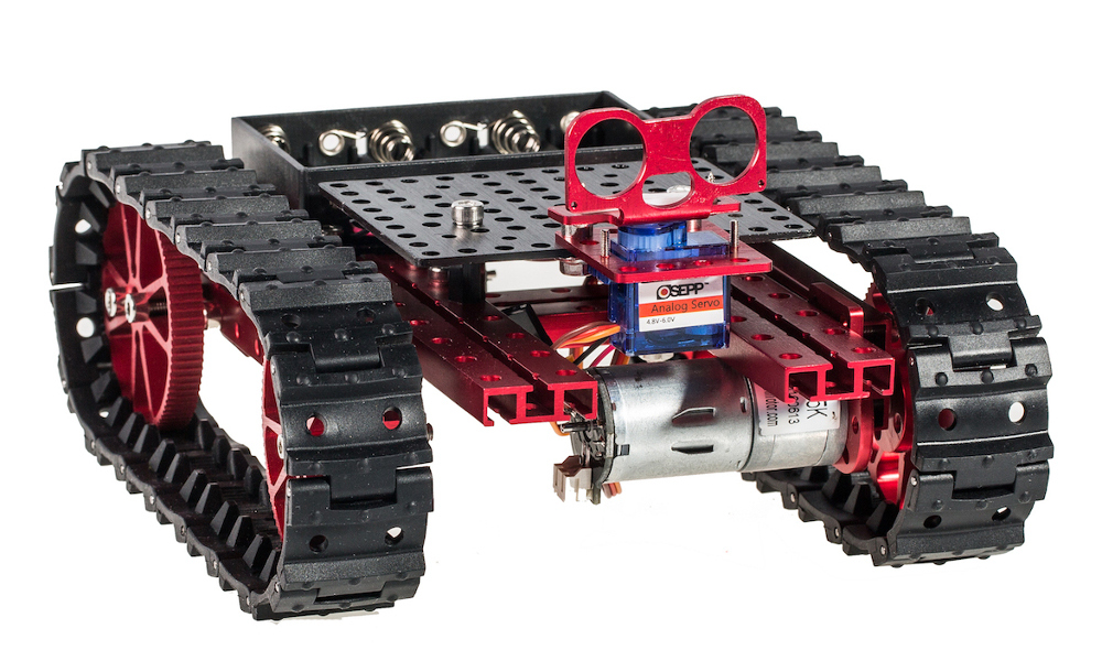
My modified OSEPP Tank Kit provided a horizontal area to mount parts but I’d have to drill into the aluminum1 and that seemed rather inflexible, and the mounting holes of the various components didn’t match that of the OSEPP beams, which use a 16mm grid.

I wanted to mount my components on something lightweight and non-conductive, cheap, and easy to modify and/or replace. Some kind of plastic seemed right. I could have used used acrylic (called “perspex” here in New Zealand) but it tends to be rather brittle and easy to crack or split, so I settled on Delrin (a trade name for polyoxymethylene plastic), which is a bit softer, tougher, and almost indestructible. Delrin is often used for making bearings.

The Lower Bits

One thing I learned long ago: it’s all very well to be able to build something but you also need to be able to disassemble it easily. I figured that I needed some way to gather the various wires from the motors and motor encoders in such as way that I could use detachable cables to easily remove the top platform from the chassis. So one principle I’m using on the KR01 is to try to use jumper wires and single and dual header pins for the connections, so that things don’t have to be permanently soldered together.

chassis interface pinout
Chassis Interface Board pinouts

For what I decided to call the Chassis Interface Board I planned to use two 6 pin IDC cables for the connections to the upper part of the robot and one of the AdaFruit Perma-Proto boards to hold all the parts and organise the wiring, which just happened to fit into the area available. I mapped out the pin layout and then soldered some header pins to the board. I also cut a bit of 10mm aluminum “L” section to hold the SPST power switch, the DPDT motor kill switch, and a status LED (you can see this in the photo below).

chassis interface board
The Power Controls (left) and Chassis Interface Board (right)

I ended up drilling two small holes (the horror!) in the aluminum rails to hold some nylon standoffs, then mounted the Chassis Interface Board and wired things up.

Even with all my planning I didn’t get it right the first time and had made a wiring mistake. Apart from the mistake, now that I’m done with these components, the nice thing is that because I’ve not soldered everything together (except in creating the components themselves) I can take it all apart when I decide to make a design change. And that’s bound to happen.

The Platform

I decided to mount my components onto a black Delrin platform using nylon standoffs, so I bought an assortment of 2.5mm black nylon standoffs from Adafruit there’d be no issue with short circuits. A robot used for off-road or robot combat might need to use metal for strength, but the KR01 is strictly a domesticated house robot2

The closest plastics store in Petone didn’t carry sheet Delrin but Macplas up in Auckland did. After a brief phone conversation about which plastics were most appropriate for a small robot, I ordered some black 3mm Delrin for the platform and some clear 3mm polycarbonate for the front bumper. I find that when you involve people in the details of what you’re doing they can use their expertise to best help you.

component layout
Component Layout

Rather than start with the Delrin (which is kinda expensive) I prototyped the board first using a milky white nylon chopping board I bought at the Warehouse for $5. Yes, it occurred to me that I could have just used the nylon but the Delrin is thinner and much cooler. I mean, who makes a robot out of a chopping board?

I taped some paper to the plastic and laid out the various components, then drilled the holes. They say “measure twice, cut once” but I still made a mistake. So maybe it should be “measure thrice, cut once”, 3

Stuff Begins Arriving in the Post…

Early Prototype

This article is the second in the multi-part series “Building the KR01 Robot” ( 1 | 2 | 3 | 4 ), and describes beginning to design and build the hardware of the KR01 robot project.

Inspired by David Anderson’s SR04 robot (in particular, his YouTube video) I searched around for a suitable robot platform, the kind of chassis and motor that fit the scale of the design-in-my-head, and a few other factors. Having read David’s documentation of the project I rather liked his “very loose” design criteria:

  1. Survive in a wide range of (cluttered) human environments autonomously and continuously, without getting stuck.
  2. Provide a robust and reliable platform for developing navigation and behavior software.
  3. Be entertaining and aesthetic for the local human population.

I thought I’d have a go at updating what he’d done in 1998 to see what 22 years might have brought to progress in the world of “personal robots”. I’d been perusing the AdaFruit and Pimoroni websites and had seen all manner of pretty amazing sensors for prices I could afford. It was time to stop making Raspberry Pi night lights and try something more ambitious.

I admit to having strayed from one of David’s stronger design principles in the SR04, that being his “dual-differential drive platform with the geometry of an 11 inch circle” 1. That symmetry is valuable and I’m hoping that my tank-tread design (or four wheels if the treads don’t work out so well) won’t suffer. Watching the SR04 rotate continuously on a table without moving in place is pretty impressive. But I have to start somewhere. I can always modify the design…

OSEPP Tank Kit
The OSEPP Tank

So, I settled on an OSEPP Tank Kit. It’s a bit like Lego or Meccano in that the kit is provided as a set of red-anodised aluminum beams, some accessory plates and connector bits, using 4mm nuts and bolts to hold things together. There’s some flexibility in this, and OSEPP sells accessory kits. I bought an extra set of beams, as I knew of one deficiency in the Tank Kit I wanted to immediately change: it has four wheels but only two motors: the port motor at the front, the starboard motor at the rear.

Since David’s design uses a PID Controller I knew I’d need to use motor encoders, which was one of the reasons I chose the OSEPP kit: they offer a pair of motor encoders using Hall Effect sensors. I’d seen an image of two OSEPP motors and encoders mounted along a single beam, quite an elegant design. It seemed prudent to have both of the encoders on the same pair of motors (either the front or the rear). The Tank would have to be wider and I also wanted four drive motors, not just two. Using tank treads is not very efficient so I figured there’d be insufficient horsepower to drive a robot with only two.

In New Zealand orders from overseas can take anywhere from a few days to weeks in waiting, so I started making decisions and putting in orders. Locally I bought some stainless 4mm hardware from Mitre 10 and Coastal Fasteners. (See Vendors on the NZPRG wiki.)

The Kit Arrives

I’m not going to do one of those ridiculous unboxing videos. Yes, the box arrived. I opened it. I didn’t keep track much with videos or photos. I was playing, not performing.

prototyping in the kitchen
Playing on the Kitchen Table

The OSEPP kit is well-designed, though it’s impossible not to leave a bit of rash on the red anodisation. If you simply built the Tank Kit as intended this wouldn’t be an issue so much, but I tried at least four or five different permutations before settling on one design, and then had to modify it several times when I tried adding things like the front bumper supports and the mount for the power switches.

Beautifully Machined Wheels

The hardware is fun to work with. Not like Lego, where it can be a struggle to connect things securely, the OSEPP kit’s parts are held together by 4mm stainless steel nuts and bolts.

I locally sourced some stainless lock nuts (also called “nyloc nuts”) as I prefer them to the serrated flange nuts provided with the kit (though these work just fine too).

The Motor Encoder kit hadn’t arrived so I built it without remembering that photo I’d seen with the single beam holding both two motors and their encoders. The design as shown above on the kitchen table had no place to mount the encoders. The photo below shows each pair of motors mounted to a single beam, with the motor encoders attached to the front (top) pair.

Front and rear pairs of motors, you can see the encoders mounted on the motor shafts of the front pair. The left and right motors are wired together so they’ll appear as a left drive and a right drive.

When the motor encoders finally arrived I did another round of building and came up with what I thought was the final chassis, but even that had to change once I tried to mount the tank treads. As you can see, there’s not much clearance between the front bumper and the treads. And of course, the front bumper was only a stand-in until I could begin building the real bumper.

Next time: we begin the wiring and mounting the platform for the circuitry…